Published: July 10, 2026Updated: July 14, 2026Read Time: 15 min readBy Mauricio L.
Share:
Link Copied!Ready to share.
Cubic Yard Volume27 Cubic Feet
Ready-Mix Cost per Yard$140-$180
80 lb Bag Cost$6.00-$8.00
ACI Joint Spacing Limit24x to 30x Slab Thickness
Minimum Curing Duration7 Days (Moist Cured)
Highlights
[ NOTE // 01 ]
Successful concrete installation requires rigorous adherence to subgrade compaction, correct water-to-cement ratios per ASTM C387, structural reinforcement placement per ACI 302.1R, and active moisture curing for at least 7 days.
Concrete is the foundational element of modern residential and commercial hardscaping. From driveways, patios, and walkways to retaining walls, pool decks, and structural footings, concrete provides the high compressive strength and long-term durability needed to support heavy loads and resist weathering. However, achieving a permanent, crack-free installation requires more than just pouring a wet mixture into wooden forms. It demands an engineering-grade understanding of subgrade preparation, material specifications, steel reinforcement placement, finishing techniques, and chemical curing kinetics.
Whether you are planning a DIY project, estimating materials for a landscape overhaul, or reviewing quotes from professional contractors, this guide provides a detailed, technical manual for concrete and hardscaping systems. To automate your planning, you can utilize our concrete calculator, estimate driveway projects with our driveway calculator, determine retaining wall blocks with our retaining wall calculator, or calculate surrounding materials using our area calculator and mulch calculator.
The Critical Pillars of Concrete Quality
High-performing concrete slabs depend on four essential steps: (1) Subgrade Compaction: Creating a uniform, non-yielding gravel base; (2) Water-Cement Ratio: Restricting water to maintain high compressive strength; (3) Mid-Depth Reinforcement: Elevating steel rebar on chairs so it resists tensile stresses; and (4) Active Moisture Curing: Preventing early evaporation so the cement can chemically hydrate to its full capacity.
1. The Chemistry & Specifications of Concrete Mixes
To execute concrete projects correctly, one must first understand the distinction between cement, concrete, and mortar, which are frequently confused:
Cement: The active chemical binder. Most modern construction uses Portland cement (defined by ASTM C150), which is manufactured by heating limestone, clay, and shale in a kiln to form clinker, which is then ground into a fine powder with gypsum.
Concrete: A structural matrix composed of Portland cement, water, fine aggregate (typically sand meeting ASTM C33 standards), and coarse aggregate (crushed gravel or stone meeting ASTM C33 standards).
Mortar: A workable mixture of cement, water, and sand (no coarse aggregate) used to bind masonry units like brick, block, or stone together, or as a bed for stone paving.
The Hydration Reaction
Concrete does not harden by "drying." Instead, it gains strength through a chemical reaction called hydration. When water is added to Portland cement, the calcium silicates in the cement react to form calcium silicate hydrate (C-S-H) gel and calcium hydroxide. The C-S-H gel is the glue that binds the aggregates together. The chemical equation representing the hydration of tricalcium silicate ($2\text{Ca}_3\text{SiO}_5$), the primary strength-giving compound in cement, is:
Because hydration is exothermic (generates heat) and requires moisture, the presence of liquid water must be maintained within the concrete matrix during the initial curing phase. If the water evaporates too quickly, the hydration process stops, resulting in weak, chalky concrete that is prone to surface scaling and structural failure.
ASTM C387 Packaged Dry Mix Specifications
For smaller projects, pre-blended dry bags are the most practical option. These products are governed by ASTM C387 ("Standard Specification for Packaged, Dry, Combined Materials for Mortar and Concrete"). This standard establishes strict minimum compressive strengths and water requirements for packaged concrete and mortars:
Mix Class / Type
ASTM Standard
Min. Compressive Strength (7 Days)
Min. Compressive Strength (28 Days)
Typical Application
Normal Strength Concrete
ASTM C387
2,500 PSI
4,000 PSI
Patios, walkways, slab footings
High Strength Concrete
ASTM C387
3,500 PSI
5,000 PSI
Driveways, heavy load pads, structural columns
Mortar Type M (High Load)
ASTM C270 / C387
N/A
2,500 PSI
Retaining walls, below-grade foundations
Mortar Type S (Medium Load)
ASTM C270 / C387
N/A
1,800 PSI
General structural masonry, exterior paving joints
The Water-Cement (w/c) Ratio
The single most critical variable governing concrete strength and permeability is the water-to-cement ratio (w/c), calculated by dividing the weight of mixing water by the weight of cement.
Low w/c Ratio (0.40 to 0.45): Creates highly dense, high-strength concrete. There is just enough water to chemically hydrate the cement particles, leaving minimal capillary pores when the excess water evaporates. This density makes the concrete highly resistant to water infiltration, freeze-thaw damage, and structural cracking.
High w/c Ratio (0.55 and above): Occurs when installers add excessive water to make the concrete flow easily. While easy to pour, the excess water occupies space in the matrix. When it eventually evaporates, it leaves behind a network of microscopic void channels (capillary pores). This reduces compressive strength, increases shrinkage cracking, and allows water and deicing chemicals to penetrate, leading to freeze-thaw damage.
The American Concrete Institute (ACI) publishes ACI 302.1R ("Guide for Concrete Floor and Slab Construction"), which defines the engineering standards for residential and commercial slabs-on-ground. To build a slab that resists cracking and settlement, you must follow these detailed specifications:
Subgrade and Base Preparation
A concrete slab is only as stable as the soil beneath it. Slabs must never be poured directly onto organic topsoil, mud, or uncompacted clay. The preparation process involves:
Excavation & Subgrade Compaction: Remove all organic material and compact the natural subgrade soil. Compaction should reach a minimum of 95% of the Modified Proctor Density (ASTM D1557) to prevent differential settlement, which is the primary cause of major structural cracks.
Base/Subbase Installation: Place a 4-to-6-inch layer of compactable granular aggregate (such as crushed run gravel, road base, or ASTM D1241 structural fill). This aggregate layer serves three functions: it distributes loads uniformly, provides a flat leveling surface, and acts as a capillary break to prevent moisture from wicking up from the soil.
Moistening the Base: Before pouring concrete, the gravel base must be moistened with water. If concrete is poured onto a bone-dry base, the aggregate will suck water out of the bottom of the fresh concrete. This causes rapid drying at the bottom while the top remains wet, resulting in "curling" (warping of the slab corners) and cracking.
Vapor Retarders: Placement and Standards
For interior slabs or spaces where moisture transmission must be prevented (such as garages, basements, or potential living areas), a vapor retarder is required. It should meet ASTM E1745 ("Standard Specification for Water Vapor Retarders Used in Contact with Soil or Granular Fill under Concrete Slabs") Class A specifications, with a minimum thickness of 10 to 15 mils of virgin polyolefin plastic.
ACI 302.1R recommends placing the vapor retarder directly underneath the concrete slab, on top of the compacted gravel base. Punctuating or tearing the vapor barrier during the pour must be avoided, and all seams must be overlapped by 6 inches and sealed with specialized adhesive tape. For exterior slabs like patios or driveways, the vapor barrier is omitted to allow uniform curing downward into the gravel base.
Joint Design and Crack Control
Because concrete shrinks approximately 1/16 of an inch for every 10 feet of length as it cures, cracks are inevitable. Concrete slabs must be jointed to pre-determine where these cracks occur. ACI 302.1R specifies three types of joints:
1. Control Joints (Contraction Joints)
Control joints create weak planes in the slab, encouraging cracks to form neatly at the bottom of the joint rather than wandering across the surface.
Spacing Formula: Spacing must not exceed 24 to 30 times the slab thickness. To find the maximum distance between joints in feet, multiply the slab thickness in inches by 2 to 2.5:
Joint Spacing (Feet) = Slab Thickness (Inches) × 2 to 2.5 For a standard 4-inch patio slab: 4 × 2 = 8 feet; 4 × 2.5 = 10 feet. Joints must be spaced between 8 and 10 feet apart in both directions.
Joint Depth: The joint must be cut or tooled to a depth of at least 1/4 of the slab thickness (T/4). For a 4-inch slab, the joint must be exactly 1 inch deep. If the joint is too shallow (e.g., 1/2 inch), the crack will form outside the joint because the relief plane was insufficient.
Saw-Cutting Timing: If using a walk-behind saw, the cuts must be made within the "critical window" of 4 to 12 hours after finishing, before concrete shrinkage stresses begin. If you wait until the next day (24 hours), the slab may have already cracked internally, rendering the saw-cuts cosmetic. Early-entry dry-cut saws (like Soff-Cut) can begin sawing within 1 to 4 hours after finishing.
2. Isolation Joints (Expansion Joints)
Isolation joints allow independent movement between the slab and adjacent structures. They must be placed wherever the slab meets a rigid vertical surface, such as:
Foundation walls and footings
Structural columns
Stairs, light posts, or utility pipes
Existing concrete driveways or sidewalks
Isolation joints are created by placing a 1/2-inch-thick strip of compressible material (typically asphalt-impregnated fiberboard or closed-cell foam) prior to pouring. The material must extend through the entire depth of the slab to prevent physical bonding.
3. Construction Joints
These joints occur where concrete placement stops at the end of the workday. They must be aligned with control joints whenever possible. To transfer shear loads across a construction joint without allowing the slabs to shift vertically, steel dowels must be used. Smooth, round Grade 60 steel dowels are embedded in the first pour, greased or sleeved on one side, and then cast into the second pour, allowing the joint to open and close horizontally while keeping the surface flush.
Floor Flatness ($F_F$) and Levelness ($F_L$)
In commercial construction and high-end residential garages or basements, slabs are specified by F-Numbers according to ASTM E1155:
$F_F$ (Floor Flatness): Measures surface waviness over short distances. High $F_F$ numbers indicate a smooth surface free of bumps or troughs, which is critical for epoxy coatings or tile installation.
$F_L$ (Floor Levelness): Measures conformability to a horizontal plane over longer distances. This is controlled by the setup of edge forms and wet screed guides.
For a typical high-quality residential garage or patio, a target of $F_F 25$ / $F_L 20$ represents a standard flat, professional finish.
3. Structural Reinforcement: Rebar and Welded Wire
Concrete is extremely strong in compression but weak in tension. Its tensile strength is only about 10% of its compressive strength. When a load is placed on a slab, or when the ground swells due to moisture or freezing, the bottom and middle of the slab experience tensile forces. Without steel reinforcement, the concrete will tear and split apart.
Steel Rebar Grades and Sizes
Reinforcing steel bars (rebar) are manufactured to meet ASTM specifications (most commonly ASTM A615). The steel is classified by size and yield strength:
Grades: The grade indicates the yield strength in thousands of pounds per square inch (PSI).
Grade 40: Yield strength of 40,000 PSI. Mostly used in light residential work or where bending is required.
Grade 60: Yield strength of 60,000 PSI. The structural standard for all modern concrete and hardscaping.
Rebar Sizes: Rebar is designated by a number that represents its diameter in eighths of an inch.
#3 Rebar: 3/8 inch (0.375") diameter. Ideal for light patios, sidewalks, and pool decks.
#4 Rebar: 1/2 inch (0.500") diameter. The standard for residential driveways, retaining walls, and footings.
#5 Rebar: 5/8 inch (0.625") diameter. Used in heavy-load commercial slabs, industrial driveways, and tall retaining walls.
Welded Wire Reinforcement (WWR)
WWR (often called wire mesh) consists of cold-drawn steel wires welded in a square grid. It is designated by grid spacing and wire area. For example:
6×6-W1.4/W1.4: A 6-inch by 6-inch grid of thin wires (0.014 square inches of steel area per foot). This is light mesh, suitable for preventing cosmetic micro-cracks in walkways but insufficient for structural load support.
6×6-W2.9/W2.9: A 6-inch by 6-inch grid of heavy wires (0.029 square inches of steel area per foot). This provides moderate structural reinforcement for residential patios.
The Positioning Failure and Solution
For steel reinforcement to work, it must be embedded in the active tension zone of the concrete—typically the middle-third or upper-third of the slab.
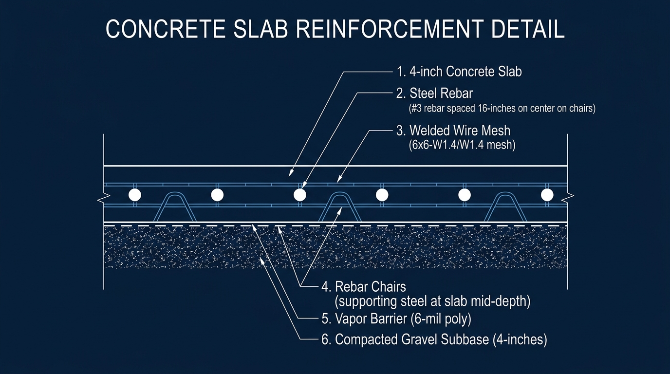
Structural Slab Cross-Section (Standard 4" Slab)
[Top of Slab Surface]  ======================================================
                        |   Control Joint Saw-Cut: 1" Deep (T/4 Depth)
                        v
                       ___
                      |   |
  (Top 1/3 of Slab)   |   |        (Concrete Mass - Compressive Zone)
                      |   |
  --------------------|---|--------------------------------------------------
                      |___|
  (Mid-Depth of Slab)        (O)  <-- #4 Rebar Grid @ 16" On-Center
                            ====  <-- Plastic Rebar Chair (Holds Rebar 2" High)
  ---------------------------------------------------------------------------
  (Bottom of Slab)

=============================================================================
[Base Layer]           4" to 6" Compacted Crushed Gravel Base (ASTM D1241)
-----------------------------------------------------------------------------
[Subgrade]             Compacted Native Soil Subgrade (95% Proctor Density)
A common contractor shortcut is to lay wire mesh directly on the ground, pour concrete on top, and claim they will "pull it up with a rake" during the pour. In practice, as soon as workers walk on the wet concrete, they step the mesh back down to the dirt. If reinforcement sits at the bottom of the slab, it provides zero structural reinforcement.
To prevent this, reinforcement must be supported on physical spacers prior to the pour:
Plastic Rebar Chairs: Clip onto the bars to hold them at a precise height (typically 2 inches for a 4-inch slab).
Concrete Dobies: Solid blocks of high-strength concrete with tie wires embedded. Ideal for heavy rebar grids because they do not sink into the gravel base and blend seamlessly with the poured concrete.
Metal Bolsters: Long wire support channels used to support steel grids in large structural areas.
Lap Splicing Standards
When individual bars must be joined to span a long slab, they cannot simply touch end-to-end. They must overlap to transfer structural tension. The minimum lap splice length is determined by the rebar diameter and concrete strength, but a standard rule of thumb is:
Minimum Lap Splice = 36 × Rebar Diameter (or 12 Inches, whichever is greater)
For #4 rebar (1/2-inch diameter), the calculation is: $36 \times 0.5 \text{ inches} = 18 \text{ inches}$ of lap splice. The two parallel bars must be tied securely with steel tie wire in at least two locations.
4. The Pouring, Finishing, and Curing Hydration Lifecycle
Pouring concrete is a time-sensitive, physically demanding process. Once the ready-mix truck arrives or mixing begins, the chemical clock starts ticking.
The Placement and Finishing Sequence
The concrete installation workflow consists of five distinct phases:
Placing: Discharge the concrete as close to its final position as possible. Do not dump it in one pile and use rakes to drag it long distances, as this separates the coarse gravel from the paste, causing structural weak spots.
Screeding (Striking Off): Use a straight-edged board (screed board) resting on the edge forms. Pull the board in a sawing motion across the top of the forms to strike off excess concrete, leveling it to the form height.
Bull Floating: Immediately after screeding, run a wide, long-handled float (bull float) across the wet surface. The blade is tilted slightly: up on the push stroke and down on the pull stroke. This embeds the coarse aggregate below the surface and brings the "cream" (cement-sand paste) to the top.
The Bleed Water Phase (Wait Period): As the concrete begins to settle, water migrates upward, forming a sheen on the surface known as bleed water. You must wait for this water to evaporate. If you edge, joint, or trowel the concrete while bleed water is present, you will force the water back into the top layer. This dilutes the cement-to-water ratio at the surface, creating a weak, porous crust that will flake off (scale or dust) during the first winter freeze.
Final Finishing: Once the bleed water has evaporated and the slab can support a worker's weight leaving only a 1/4-inch footprint, final detailing begins:
Edging: Run an edger tool along the forms to create a clean, consolidated, rounded radius that resists chipping.
Jointing: Cut control joints using a hand groover (or prepare for saw-cutting later).
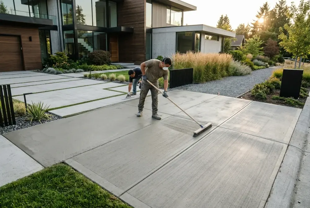
Troweling: Use steel trowels to compact the surface. For exterior slabs, a steel trowel finish is followed by a broom finish (dragging a damp broom across the surface) to create a non-slip, textured traction surface. For interior slabs, successive passes with a steel trowel create a smooth, dense, polished finish.
Curing: The Kinetics of Cement Hydration
Curing is the preservation of moisture and temperature conditions required for cement hydration. Concrete does not gain strength by drying; it gains strength by hydrating. If concrete dries out, the strength gain stops immediately.
Concrete reaches its nominal design strength at 28 days, but the rate of strength gain is highly front-loaded:
Curing Age
% of 28-Day Strength (Standard Mix)
Structural Capacity
1 Day
15% - 20%
No traffic; forms can be removed carefully
3 Days
40% - 45%
Safe for light foot traffic
7 Days
65% - 70%
Safe for light vehicles (passenger cars)
28 Days
100% (Design Strength)
Fully functional load capacity (RVs, heavy trucks)
To achieve full strength, concrete must be cured actively using one of three primary methods:
Wet Curing (Ponding or Saturated Cover): The gold standard. Slabs are kept continuously wet by spraying water, ponding, or covering them with burlap mats that are kept saturated. Saturated wet curing should be maintained for at least 7 days.
Moisture-Retaining Sheets: The slab is covered with polyethylene plastic film or waterproof paper. This seals the moisture in. However, the plastic must be laid flat and weighted down; otherwise, folds will create uneven hydration rates, leaving permanent, mottled discoloration (known as "greenhouse effect" staining).
Liquid Membrane-Forming Curing Compounds (ASTM C309): A chemical sealant sprayed onto the slab immediately after final finishing and the disappearance of the water sheen. The compound forms a membrane that blocks moisture evaporation. Curing compounds are highly effective for residential projects because they require no active watering. However, they must be removed if you plan to install tile, epoxy, or certain sealers later, as they block mechanical adhesion.
ACI 305R & 306R Weather Guidelines
Weather extremes can ruin concrete during placement and curing:
Hot Weather (ACI 305R): High temperatures (above 90°F / 32°C), low humidity, and high winds accelerate evaporation. This causes plastic shrinkage cracks, which occur while the concrete is still wet. Mitigations include: wet down the subgrade thoroughly, erect windbreaks, add retarders to slow setting, use chilled mixing water or ice, and pour during cool night or early morning hours.
Cold Weather (ACI 306R): When temperatures drop below 40°F (4.5°C), hydration slows dramatically. If fresh concrete freezes, the expansion of water into ice crystals destroys the concrete's internal bond structure, reducing its lifetime strength by 50%. Mitigations include: never pour concrete onto frozen ground, use heated mixing water and aggregates, add non-chloride accelerators (like calcium nitrite), and cover the slab with insulated curing blankets to trap the exothermic heat of hydration for at least 3 to 5 days.
5. Hardscaping Systems & Retaining Wall Engineering
Concrete is the primary structural component of hardscaping systems. A successful landscape design must integrate concrete slabs with walkways, patios, and retaining walls, ensuring proper transitions and drainage.
Retaining Wall Design and Hydrostatic Pressure
Retaining walls fail because of hydrostatic pressure, not soil weight. When rain falls, water accumulates in the soil behind the wall. Water weighs 62.4 lbs per cubic foot. If this water cannot escape, it exerts lateral pressure that pushes the wall forward, causing it to tilt, bow, or collapse.
To prevent structural failure, every retaining wall must incorporate the following drainage elements:
Compacted Gravel Footing: Walls must sit on a non-yielding foundation of compacted road base gravel, typically 6 inches deep and twice the width of the retaining blocks. The first course of blocks must be buried (embedded) below grade (1 inch of burial per 8 inches of wall height) to prevent kicking out at the toe.
Perforated Drain Pipe (Weeping Tile): A 4-inch-diameter perforated PVC pipe placed at the bottom of the gravel trench behind the wall, sloped to drain away to daylight. The pipe holes must face downward to collect rising water.
Granular Drainage Backfill: A vertical column of clean, washed angular stone (3/4-inch aggregate, no sand or dirt) at least 12 inches wide behind the wall. This gravel has high permeability, allowing water to drop straight to the drain pipe rather than pressing against the back of the wall blocks.
Geotextile Filter Fabric: A layer of non-woven geotextile fabric separating the gravel backfill from the natural soil behind it. This prevents fine silt and clay particles from migrating into the gravel and clogging the drainage system.
Weep Holes: Openings through the face of the wall at the ground line (typically spaced every 4 to 8 feet) to allow any water that bypasses the pipe to escape safely.
Hardscaping Integration: Driveways & Walkways
When building a hardscape project, ensure that concrete slabs integrate with surrounding materials. For example, a concrete patio may meet brick pavers or a flagstone walk.
Driveway Thickness & Lifespan: Driveways must be constructed to handle heavy wheel loads. Standard passenger vehicles require 4 inches of concrete, but heavy-duty parking pads or commercial accesses require 6 inches. To protect the investment, concrete driveways must be sealed periodically. Learn more about the processes, schedules, and costs in our driveway sealing cost guide. For concrete thickness calculations, see our how much concrete do I need guide.
Landscaping and Mulching: Hardscaping projects require adjacent grading and landscaping to manage erosion. After installing a patio or retaining wall, backfilling with clean topsoil and applying mulch prevents erosion and suppresses weeds. Use our mulch calculator to estimate the exact quantity needed for surrounding garden beds.
Estimating concrete projects requires converting dimensional measurements into cubic yards. A cubic yard is a volumetric unit representing a cube 3 feet wide, 3 feet long, and 3 feet deep.
1 Cubic Yard (yd³) = 3 ft × 3 ft × 3 ft = 27 Cubic Feet (ft³)
When measuring slabs, homeowners measure length and width in feet, but thickness in inches. To avoid errors, you must convert the thickness to feet by dividing by 12 before calculating volume.
The Concrete Volume Formula
To find the concrete volume of a rectangular slab in cubic yards:
Never order the exact mathematical volume of concrete. The ground is rarely perfectly flat, excavation depth varies, and wooden forms bow outward under the weight of wet concrete.
For slabs-on-grade: Add a 10% waste buffer to your order.
For irregular footings, trench pours, or rough excavations: Add a 15% waste buffer.
If your calculation yields 4.2 cubic yards, you must add 10% (0.42 yards) for a total of 4.62 yards. Round this up to the nearest half-yard, ordering 5.0 cubic yards.
Step-by-Step Calculation Examples
Example 1: A Large Residential Driveway Slab
Estimate the concrete and materials required for a residential driveway measuring 24 feet wide by 40 feet long, with a thickness of 5 inches over a 4-inch gravel base.
Understanding the financial components of concrete and hardscaping helps in budgeting and evaluating contractor proposals. The total cost of concrete depends on the delivery method, raw material upgrades, and labor requirements.
Ready-Mix Concrete Delivery Fees (2026 Rates)
In 2026, the base cost of standard 4,000 PSI ready-mix concrete ranges from $140 to $180 per cubic yard. However, several additional fees apply:
Short-Load Fee: Assessed on deliveries of less than 5 to 6 cubic yards. This flat charge ranges from $150 to $300 to offset the cost of operating a partially empty truck.
Fuel Surcharges: A variable fee (typically $10 to $25 per load) depending on travel distance and fuel prices.
Environmental Compliance Fee: A fee of $5 to $15 per load for truck washout and waste recycling.
Weekend/After-Hours Delivery: Pouring on Saturdays typically adds $15 to $30 per cubic yard in premium fees.
Additives:
Chemical Accelerator (for cold weather): Adds $5 to $12 per yard.
Chemical Retarder (for hot weather): Adds $5 to $10 per yard.
Fiber Reinforcement (synthetic polypropylene fibers): Adds $8 to $15 per yard.
High-Strength Upgrade (5,000 PSI): Adds $10 to $20 per yard over the base price.
Cost Comparison: Bags vs. Ready-Mix vs. Volumetric Mixer
Depending on the size of your project, the choice of concrete source has significant financial implications:
Source Type
Typical Unit Cost
Cost per Cubic Yard
Best Suited For
Pros & Cons
Dry Bagged Mix (80 lb)
$6.00 - $8.00 per bag
$270 - $360 (45 bags/yd)
Under 1.5 cubic yards
Low upfront cost, physical labor to mix
Ready-Mix Truck (Delivered)
$140 - $180 per yard
$170 - $220 (with delivery fees)
Over 3 cubic yards
Fast placement, high quality, short-load fees on small runs
Volumetric Mixer (On-Site Mix)
$160 - $200 per yard
$190 - $240 (only pay for what is used)
1.5 to 4 cubic yards
No waste, no short-load fees, slightly higher base rate
Installed Cost per Square Foot (Slab-on-Grade)
When hiring a professional contractor, pricing is quoted by the square foot. This price includes excavation, gravel base preparation, form setup, reinforcement installation, pouring, finishing, and control joint cutting.
Sidewalks & Walkways (4" thick, standard finish): $8.00 to $12.00 per square foot.
Standard Driveways (4" thick, broom finish, rebar grid): $9.00 to $14.00 per square foot.
Heavy-Duty Slabs (5" or 6" thick, rebar grid, base gravel): $11.00 to $16.00 per square foot.
Stamped or Decorative Patios: $15.00 to $25.00 per square foot, depending on the complexity of the pattern and the number of accent colors used.
Segmental Retaining Walls: $25.00 to $50.00 per square foot of wall face, including drainage gravel and trench work.
8. Quality Control & Contractor Procurement Checklist
If you hire a concrete contractor, do not rely on a simple verbal agreement. Concrete mistakes are permanent and expensive to correct. Ensure that the written contract specifies the following engineering parameters:
Compressive Strength: Specify a minimum of 4,000 PSI at 28 days for driveways and patios, rather than a generic "concrete mix."
Slab Thickness: Verify the target slab thickness is written (e.g., "minimum 4 inches of uniform thickness") and that the subgrade will be excavated to allow this thickness over the base gravel.
Base Layer: Require a minimum of 4 inches of compacted aggregate base (such as crushed road base gravel), rather than pouring concrete directly onto natural dirt.
Reinforcement: Specify the type and spacing of steel reinforcement (e.g., "#4 Grade 60 rebar placed in a grid at 16 inches on-center"). Specify that the rebar must be supported on plastic chairs or concrete dobies prior to pouring.
Joint Layout: Require a written control joint plan. Joints must be spaced at intervals no greater than 10 feet for a 4-inch slab, and cut to a depth of 1/4 of the slab thickness (1 inch).
Curing Method: Require the application of a liquid curing compound (meeting ASTM C309 standards) immediately after finishing, or active wet curing for a minimum of 3 days.
Pre-Pour Checklist for Homeowners
Before the concrete mixer arrives, complete a physical inspection of the forms:
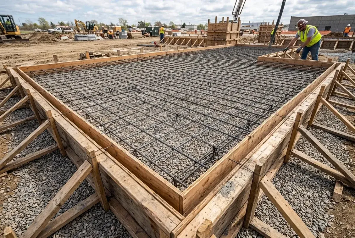
Check Form Rigidity: Wooden forms must be staked every 3 feet. Lean on the forms to ensure they do not budge. If they are loose, the weight of the concrete will push them out, resulting in bowed edges.
Verify Slope for Drainage: The slab must slope away from foundation walls to prevent water intrusion. The standard slope is 1/8 to 1/4 inch of drop per linear foot. Check this with a line level or digital transit level.
Inspect Rebar Support: Walk the rebar grid. Step on the bars. If they touch the ground and do not bounce back up onto their chairs, add more supports. The steel must be suspended in the middle-third of the slab.
Confirm Chute Access: Ensure there is a clear path for the concrete truck. A loaded concrete truck weighs up to 70,000 lbs. If it drives over existing driveways, sidewalks, or lawns, it can crush pipes and crack old concrete. If access is limited, make sure the contractor has scheduled a concrete pump or motorized buggies.
Verify Subgrade Moisture: Ensure the gravel base is damp but free of standing water. If it is dry, spray it with a hose right before the pour.
Frequently Asked Questions
What is the difference between cement, concrete, and mortar?▼
Cement is the active chemical binder (usually Portland cement) made of limestone and clay. Concrete is a structural mixture of cement, water, fine aggregates (sand), and coarse aggregates (gravel or crushed stone). Mortar is a bonding mixture containing only cement, water, and sand (no coarse aggregate), used to bind bricks or stones together.
How long must concrete cure before it can support vehicle traffic?▼
Under standard conditions (above 50°F), concrete should cure for a minimum of 7 days before light vehicle traffic (standard passenger cars) is permitted, and 28 days for heavy vehicle traffic (delivery trucks, RVs). Foot traffic is generally safe after 24 to 48 hours.
Should I use rebar or welded wire reinforcement (WWR) for a residential driveway?▼
For a residential driveway, #3 or #4 steel rebar placed in a grid (typically 16 to 18 inches on center) is superior to light welded wire reinforcement (WWR). WWR is often improperly placed (stepping on it during the pour pushes it to the bottom of the slab, where it provides no structural benefit). Rebar tied on chairs remains securely at the mid-depth of the slab.
Why does concrete crack, and can it be completely prevented?▼
Concrete naturally shrinks as it cures and loses excess water, which builds up internal tensile stress. Since concrete's tensile strength is low, it will crack to relieve this stress. You cannot completely prevent cracking, but you can control where it occurs using saw-cut control joints (contraction joints) spaced at 24 to 30 times the slab thickness, and limit cracks with proper water-cement ratios and steel reinforcement.
Is it safe to pour concrete in freezing weather?▼
Pouring concrete is risky when temperatures drop below 40°F (4.5°C). If fresh concrete freezes before reaching 500 PSI compressive strength (typically within the first 24-48 hours), its ultimate strength is permanently reduced by up to 50%. Cold weather pours require ACI 306R measures, including heated aggregates, chemical accelerators, and insulated curing blankets.
What is the ideal thickness for concrete driveways and patios?▼
Patios, walkways, and trash pads meant only for pedestrian traffic should be at least 4 inches thick. Standard residential driveways carrying passenger cars should also be 4 inches thick, but 5 to 6 inches is highly recommended for heavy SUVs, delivery trucks, or RV parking pad zones. Slabs must have a uniform thickness over a compacted gravel subbase.
How often should I seal my concrete driveway or patio?▼
Exterior concrete should be sealed every 2 to 3 years. Penetrating silane-siloxane sealers are ideal for driveways as they protect against moisture and deicing salt damage without altering the surface texture. For decorative or stamped concrete, acrylic topical sealers are used to enhance color and shine but require more frequent maintenance. For asphalt driveways, refer to our driveway sealing cost guide.
What is a 'short load' fee in ready-mix concrete delivery?▼
Ready-mix suppliers generally require a minimum order of 5 to 6 cubic yards to cover the fuel and operational costs of their trucks (which carry up to 10 yards). If you order less than this minimum, you will be assessed a 'short-load fee,' which typically ranges from $150 to $300 per delivery, in addition to the standard yardage rate.
§
Research Citations & Verified Authorities
EEAT Compliant
To maintain absolute calculation integrity and trust, the structural lifespans, standard sizes, and pricing models in this guide are gathered from governing construction authorities and verified trade standards.
American Concrete Institute (ACI) Committee 302 - Guide for Concrete Floor and Slab ConstructionAudit Source →
ASTM International - Standard Specification for Packaged, Dry, Combined Materials for Mortar and Concrete (ASTM C387)Audit Source →
Portland Cement Association (PCA) - Design and Control of Concrete MixturesAudit Source →
Mauricio L.
// Creator of Meazora
Mauricio L. is a software developer who loves working with his hands. He built Meazora because he was tired of online calculators that exist just to capture your email and phone number. Every calculator here runs completely in your browser to keep your planning private, fast, and simple.